Description
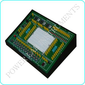
It is very useful in power electronics laboratories for performing power experiments in colleges and universities. It is very for student to know about the characteristics of power electronics devices and the applications of power devices. The applications or power devices are in alarm circuit, lamp flasher, rectifiers, choppers, inverters. It is also used for commutation circuits.
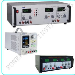
| DC Power Supply on Board |
5V at 100mA 12V at 150mA 15V at 50mA 35V at 50mA |
| AC Power Supply on Board |
18V – 0V – 18V at 50mA 15V – 0V – 15V at 50mA |
| Triggering Circuit on Board |
5 gate signal output Frequency range : 40Hz to 900Hz Variable Amplitude : 12V PWM control of G1,G2,G3 and G4 Duty cycle control of Gate Signal is 0 to 100% |
| Single Phase Rectifier |
Firing angle control 0-180 variables |
| Firing Circuit on Board |
Four gate signal output with isolation |
| SCR Assembly |
4 SCRs 2P4M, 600V,2A |
| Power Devices |
IGBT-G4BC20S, MOSFET-IRF540, UJT-2N2646, DIAC-DB3, TRIAC-BT136, PUT-2N6027 |
| Circuit Components On Board: |
Capacitor 0.01uF, 0.047uF , 0.1uF, 0.33uF, 1uF/63V(4Nos.) 2.2uF/50V Diode 1N4007 (8Nos.) Zener Diode 9V (1Nos. ) Inductors 10mH, (1Nos.), 68mH (2Nos.) Load Resistance 120E, 270E, 1K, 2K2, each 5W Resistance on Board ( W) 22E/5W, 100E/2W, 220E/2W Resistance on Board(1/4W) 10K (3Nos.), 22K,33K,47K, Potentio Meter 4K7(2Mos.), 1M(1Nos.) |
| Pulse Transformer on Board |
2 Nos. PT4502, 1:1 and one is PT4503 1:1:1 |
| Toggle Switch |
SPST (1Nos.) |
| Power Requirements |
220V 10%, 50Hz |
- Make : Omega
For more details, Contact : shanmugam@powerlabinstruments.com