Description
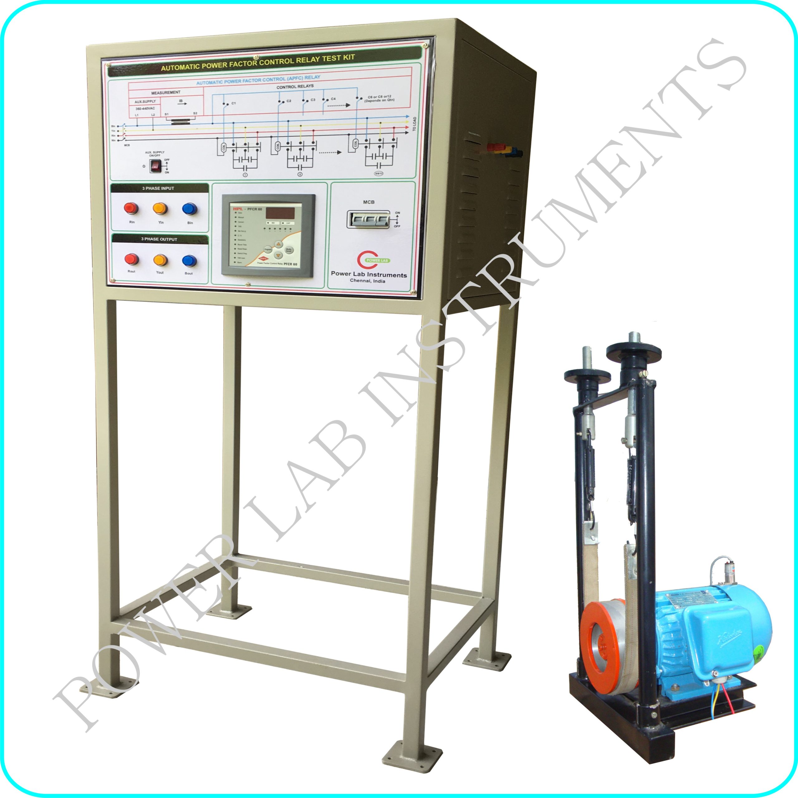
This set up is designed to study the working principle of Power Factor control system in 3 phase Motor Load using APFC (Automatic Power Factor Control) Relay. It consists of
- APFC Relay with Capacitor
- 3 Phase Motor Load
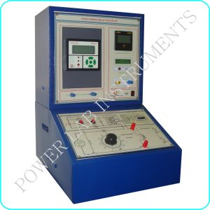
- Panel set up
APFC Relay with Capacitor : HPL Make /6 or 8 stage
- Micro controller based design & Effective PF control for balanced loads
- Capacitor Bank selection 6 / 8 stage
- Auto ( or) Manual operation
- Front panel digital display for PF & Voltage Input 415V Ac ± 20%, 50 Hz
- Current Input 5A / 1A from CT secondary (Field selectable)
- Desired PF setting 0.8 lag to 0.95 lead
Capacitor
- 6 sets of 3 phase power Capacitor ( 6 stage or 8 stage) is provided
3 Phase Motor
- Type 3Ø squirrel cage induction Motor
- Power 1 hp
- Voltage 3Ø, 415VAC
- Speed 1440 RPM
- Loading spring balance loading arrangements with dial indication and brake drum
- Make CG / SIEMENS/BALDOR
Panel with meter
- One number powder coated panel with mimic diagram is printed on front panel
- APFC Relay is fixed on the panel with necessary termination for external connection
- Necessary MCB , Switch & indicators are provided
- Banana terminals for 3 Phase AC input & Load Output
For More Details , Contact : shanmugam@powerlabinstruments.com