Description
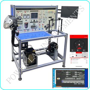
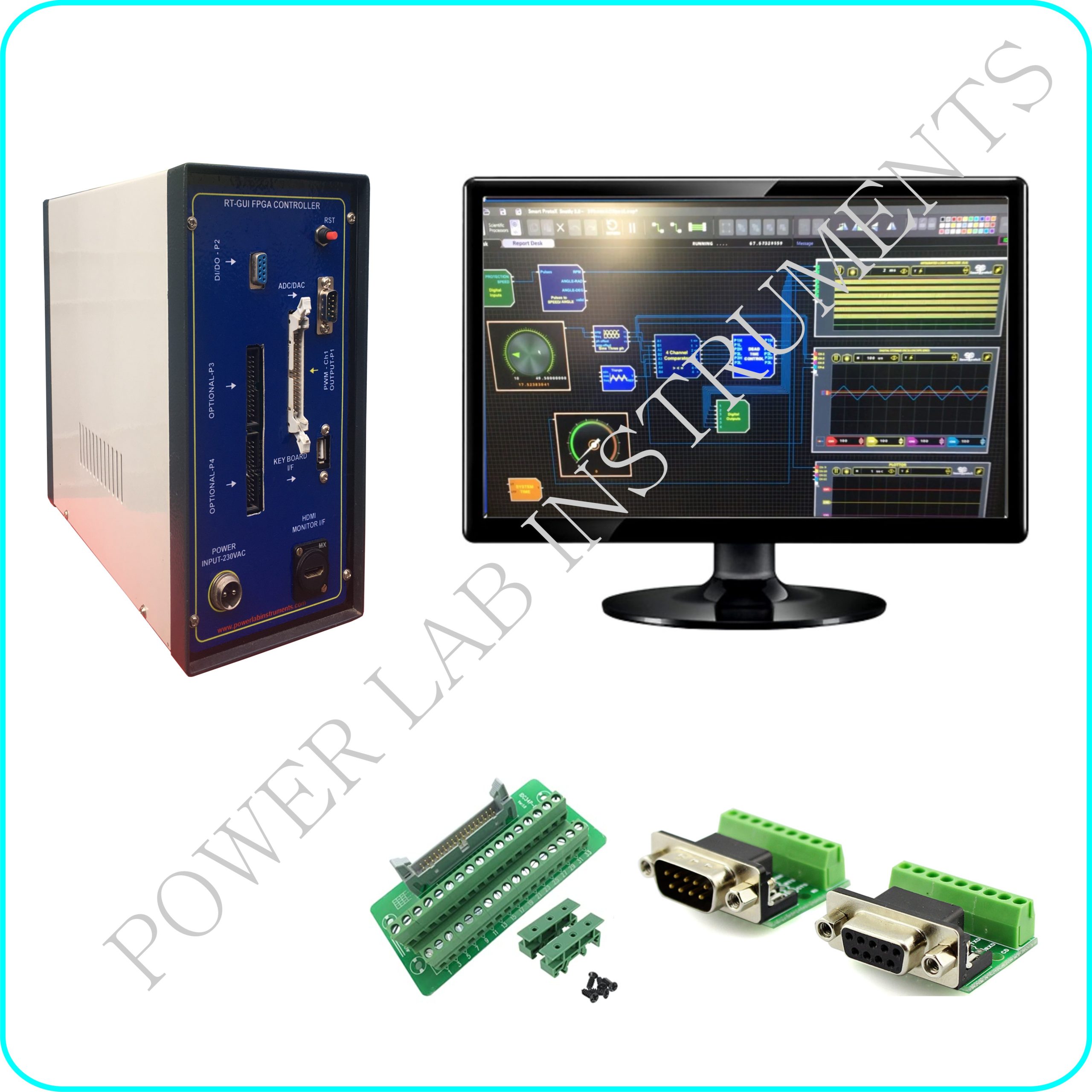
The FPGA-Real Time controller is a ready-to-use, high-performance, real-time testing platform with built-in analog and digital I/O channels. It includes all required cables, terminal boards, and adapters to enable easy connectivity from the target machine I/O to your hardware under test.
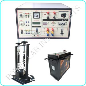
This controller can be used to generate PWM Signals for SCR, IGBT based power electronics application like DC-AC Inverter ,DC-DC Chopper & SCR converter based AC/DC/BLDC Switched Reluctance Motor (SRM) control application. PWM output of this controller can be interfaced with Power Module through External cable connection
FPGA Features
- FPGA Device : Artix-7/Xilinx FPGA-XC7A200T
- Number of Clock Sources : 1
- Primary Clock Frequency : 100MHz – (150MHz converted inside FPGA using internal PLL)
- Number Of GPIOs (Max) : More than 100
- Configuration Options : USB 2.0 interface for On-board flash programming, JTAG
- Configuration Memory : Flash memory-256 Mb SPI flash memory (S25FL256S)
- Internal RAM : DDR3-512MB (MT41K256M16HA)
- Power supply : On-board voltage regulators for single power rail operation
PWM Outputs & Digital I/O’S
- 12 numbers of PWM output @ 5V logic level ( 3.3v to 5V level converter is provided)
- 4 numbers of Digital input @ 5V logic level is provided for speed sensor interface / Motor feedback (hall sensor) interface
- Additional PWM output card -72 Channel PWM output (@Optional cost)-Depends on customer requirements
ADC/DAC
- 3 Channel SPI based ADC (12 Bit)
- 3 Channel SPI based DAC (12 Bit)
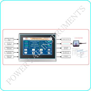
GUI Blocks
- Hardware Interface Blocks :
- PWM / Digital Output Blocks – 12 basic (Optional 72 at additional cost)
- Digital input Blocks – 12
- ADC Block – 3 Channel
- DAC Block – 3 Channel
- Other Functional Blocks : Knob – ON/OFF Switch – Gauge block -scope-display-etc, Frequency Counter-Speed estimator-Filter-PID Controller, Dead Time Controller, SCR Trigger Pulse controller, Sources : Constants-Sine wave generator (Multiphase)-Triangle wave-Square wave-saw tooth wave-svpwm-dc pwm-BLDC Look up table-user-configurable Lookup table etc, Others : Logic Gates-Comparator-Mux-Demux-Delay-Math Function-User Logic-Clarke/inverse clarke transformation-park-Inverse Park- etc,
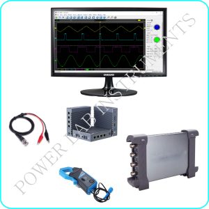
- Measuring Instruments / Control Blocks, Built in 8 Channel DSO, Built in 14 Channel Logic Analyzer, Built in 04 Channel Plotter, Built in 08 Channel Digital Display, Built in 04 Channel Gauge (VI), Built in 04 Channel Knob (VI), Built in 08 Channel Toggle Switch(VI), All DSO, Plotter, analyser -Time & Amplitude adjustments, All Knob’s & Gauge values are user configurable
- Waveform Report – Option to send waveform image to user (using mail or Bluetooth or USB-card). Option to send waveform sample data’s as CSV file to user (using mail or Bluetooth or USB-card)
Accessories
- 24inch LCD/LED Monitor-HDMI Port
- Mouse – wireless
- 15 Pin Connector Break out Board
- 9 pin Connector Break out Board
For more details Contact : shanmugam@powerlabinstruments.com