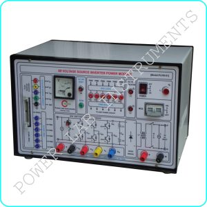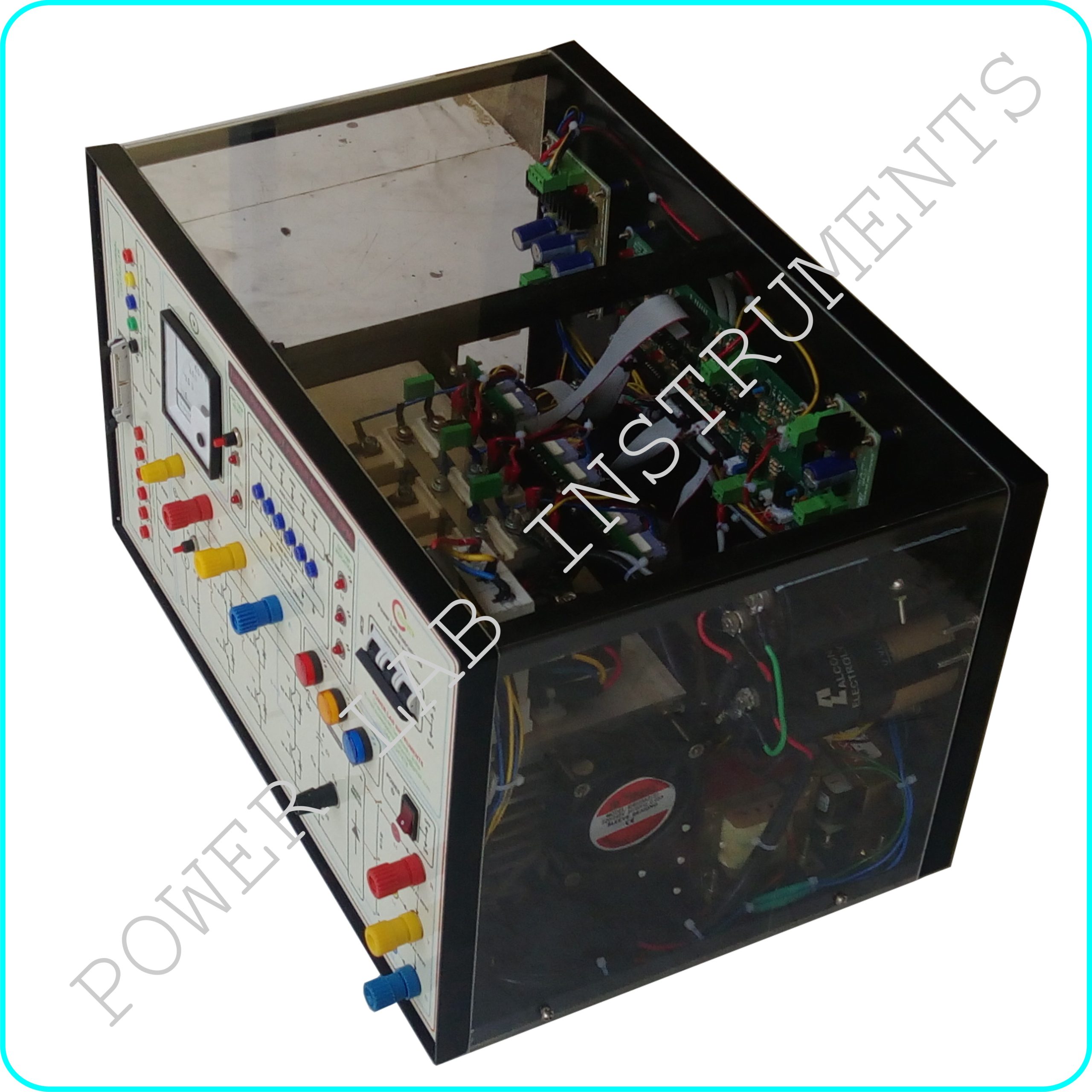
Description
This power module is designed by using SEMIKRON –IGBT for AC/DC/BLDC Motor control / Cascaded type Multilevel inverter application. This power module can be used for AC, DC, application by proper external PWM controller interfacing (like Dspic , FPGA & DSP). This Module consists of
Specifications
Power Circuit
Input :- 3 PHASE 0- 415VAC , 50 HZ (or) 0-600VDC
Output :-1 Ø /3Ø, 400V , Variable Voltage , Variable frequency ( OR) 0 +/- 580VDC
Capacity:- 3KW
PWM Section
Number of PWM Input:- 6
Maximum PWM Frequency:-15 KHZ
PWM Level :- 0-3.3/5V (TTL)
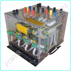
- Three Number of IGBT-IGBT Power Module Rating @ 1200V , 160A based three phase Voltage source inverter Power circuit
- Model : SKM 100 GB12T4 (REFER ATTACHED DATA SHEET)
- IGBT is fixed with suitable heat sink and snubber circuit for protection
- IGBT Power circuit input and outputs are terminated by suitable rating banana connectors in front panel with necessary indication
- One number of 3Ø diode rectifier ( 1200V @ 150A ) is provided to converter input AC voltage to DC Bus voltage with discharge resistor
- DC Capacitor is provided ( centre point type) at diode rectifier output side for Filter
- Analogue DC Voltmeter ( 0-600VDC) is provided to measure DC Bus voltage
- Six Number of PWM Isolator IC (6N137) is used to isolate All the six PWM signals input
- One number of +15V@1amp fixed dc power supply is provided for PWM Isolator input side for power excitation
- One number of +5V@1amp fixed dc power supply is provided for PWM Isolator Output side power excitation
- IGBT Gate Driver is provided for IGBT Gate signal amplification./Model SKYPER 32
- 3 numbers of Hall effect current sensor @ 25A is provided for 3Ø output AC/DC Current measurement
- 1 numbers of Hall effect current sensor @ 25A is provided for Input DC bus Current measurement
- Op-Amp based Signal conditioner circuits are provided in all sensors for output current signals amplifications
- All current sensor signal conditioner circuit outputs are terminated in front panel by suitable connectors
- One number of automatic trip circuit is provided for O/C protection
- LED is provided for trip status indication
- Reset switch is provided for TRIP RESET
- One number of 34 pin FRC Connector is provided for PWM input signal input and feed back
- Banana connectors are provided for 3 Phase AC input & 3 phase output
- Test points are provided for PWM signal and Current wave form measurements
- MCB is provided at input side for Input supply ON/OFF
For More Details , Contact : shanmugam@powerlabinstruments.com